Answer up front: what to check before replacing a faulty engine sensor
Before buying or fitting a replacement, confirm the fault with an OBD2 code and live-data check, visually inspect the sensor and wiring, test the sensor’s reference voltage and ground, perform a bench or in-place sensor test if possible, and consider programming/calibration requirements. Most “faulty sensor” swaps fail to fix the problem because the underlying wiring, connector, or ECU reference is bad, not the sensor itself.
Why start with codes and live data
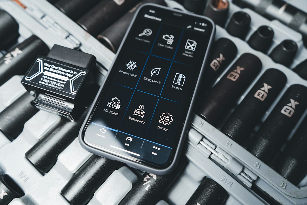
Clear action first: plug in a scanner and read stored and pending trouble codes. Codes identify which circuit the car thinks is wrong (e.g., P0102 Mass Air Flow – Low Input) but they don’t always prove the sensor is dead. Use the scanner’s live-data (PID) stream to watch the sensor output while the engine is idling, revving, and under load. A healthy sensor normally moves smoothly and responds to conditions; a stuck, erratic or out-of-range reading helps justify replacement.
Inspect connectors and wiring—don’t skip this
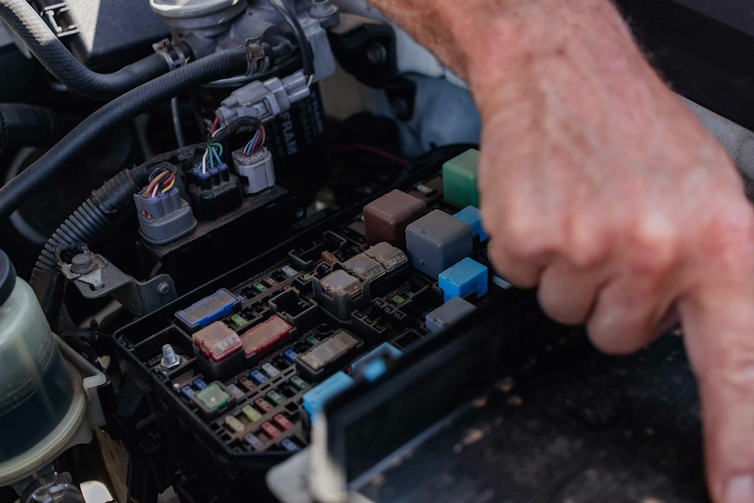
Open the sensor plug and inspect the pins for corrosion, bent pins, or pushed-back terminals. Exposed or frayed wires, rubbing points near the manifold, or heat-damaged insulation are common causes of intermittent faults. Wiggle the harness while observing live data or the check-engine lamp: if the value jumps or the code toggles, the problem is likely wiring or connector fatigue rather than the sensor element.
Test the reference voltage and ground
Many sensors use a 5V or 12V reference and a dedicated ground. Using a multimeter, verify the reference voltage at the connector with ignition on (engine off) and confirm a solid ground continuity to chassis. A weak reference (<±0.2V for 5V systems) or high-resistance ground will produce erroneous readings across any replacement sensor. If the reference is missing or unstable, trace back to the ECU or harness splice before replacing the sensor.
Perform a functional or bench test
Where feasible, test the sensor directly. Some sensors (e.g., temperature, MAP, throttle position) can be stimulated—warm a temp sensor with a heat gun and watch the resistance or voltage change; apply a vacuum to a MAP sensor and note the output shift. For sensors that are cheap and easily swapped, bench tests are less important, but for expensive components or sensors requiring calibration (like some cam/crank or NOx sensors), a proper functional test can save time and money.
Watch for intermittent faults and related systems
Intermittent faults need patience. Recreate the operating condition that triggers the code—cold start, hot soak, acceleration—and monitor live data during the event. Also consider linked systems: a faulty MAF can cause fuel trim faults; a bad manifold leak can mimic many sensor issues. Use related PIDs (fuel trims, long/short term, RPM, intake pressure) to see whether the sensor reading is an isolated anomaly or part of a broader symptom cluster.
Consider ECU/software and calibration needs
Some sensors require an ECU relearn or calibration after replacement (throttle position, steering angle, certain NOx/DPF sensors). Check the service manual or tech notes for the vehicle. If a post-replacement relearn is required and not performed, the vehicle may show persistent faults even with a good sensor. In modern vehicles the ECU can also adapt—clear codes, run the car through drive cycles and re-check before declaring success.
Decide whether to replace or repair the circuit
If inspection and tests point to wiring, connector repair is usually preferable to sensor replacement. Repair options include replacing the terminal pins, using a pigtail harness, repairing chafed sections, or installing heat-sleeved wiring near hot areas. If the sensor itself fails bench tests or the live data flatlines, replace it with an OE-equivalent part and keep the original for comparison if warranty matters.
Choosing a diagnostic tool and one recommended product
For most DIYers and independent shops an OBD2 scanner with live-data and DTC clearing is essential; it prevents needless part swaps. The Autel OBD2 Scanner MS309 (ID 570) is a strong fit for standard OBD-II vehicles and provides codes and live-data capabilities suitable for confirming sensor faults before purchase.
Practical exceptions and tricky sensors
Crank and cam position sensors, wheel speed sensors on ABS rings, and NOx/O2 sensors can be tricky: magnetics, tone rings, contaminated elements, or ECU-side pull-up circuits can masquerade as sensor failure. For sensors that rely on mechanical alignment or air passages, check physical mounting, tone ring damage, vacuum hoses and intake leaks first. Also note that sensors exposed to contamination (oil, exhaust soot) should be inspected for contamination that can often be cleaned rather than replaced.
- Read stored/pending DTCs and capture live PID data during the fault condition.
- Inspect plug pins, seals and harness for corrosion, heat or chafing.
- Measure reference voltage and ground continuity at the connector.
- Perform a functional or bench test when possible (heat, vacuum, resistance).
- Check for related system symptoms (fuel trims, intake leaks, wiring shorts).
- Confirm any required ECU relearn or calibration after replacement.
Don’t replace a sensor because a code appeared—verify with live data and basic electrical tests first. Often the fix is a connector, ground or wiring repair; when a sensor is actually bad, choose an OE-equivalent part and perform any required relearn.
Can I rely on the check engine light code to identify a bad sensor?
Codes point to a circuit but don’t prove a failed sensor. Use live-data and electrical tests to confirm the sensor’s behavior before replacing it.
How do I test sensor wiring without removing the sensor?
Measure the reference voltage and ground at the sensor connector with the harness connected; wiggle the wiring while watching live PID or the check-engine lamp for changes.
When should I replace the connector instead of the sensor?
If pins are corroded, terminals are loose or insulation is damaged, repair or replace the connector first—these faults often cause intermittent codes that a new sensor won’t fix.
Do all sensors need calibration after replacement?
No—many simple sensors do not, but throttle bodies, steering angle sensors and some emissions sensors can require a relearn or software update; check the vehicle service info.
Which diagnostic scanner features are most useful for this work?
Live-data/PID streaming, freeze-frame viewing, DTC reading/clearing, and basic graphing are the most helpful features when diagnosing sensor problems.