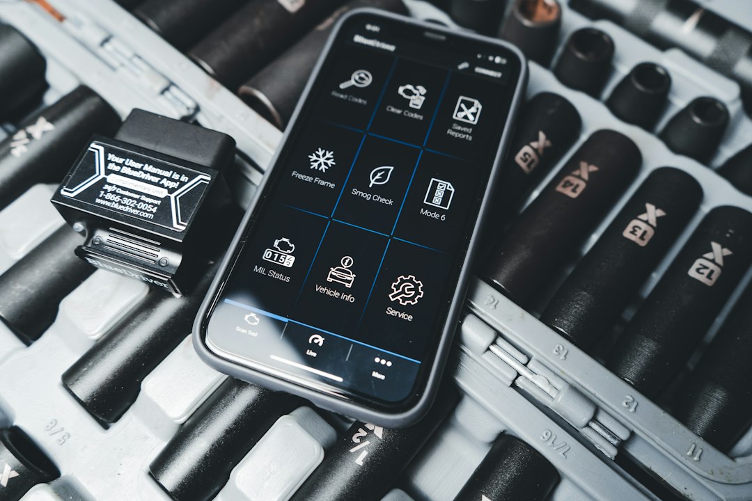
Short answer: use live PIDs to separate sensor, actuator and mechanical throttle faults
Start by watching live throttle-related PIDs—throttle position sensor (TPS), throttle plate angle (if present), target throttle angle, engine RPM, and intake vacuum or MAF—while commanding the throttle and at idle. Comparing commanded vs. actual positions plus RPM and vacuum response tells you whether the problem is electrical (sensor or wiring), mechanical (sticking plate, carbon), or control-software related (adaptation, closed-loop faults).
What you need and why each item matters
- OBD2 scanner capable of live data and (ideally) bi-directional controls — you need to read PIDs and with better tools command the throttle or run relearn routines.
- Basic hand tools and cleaning supplies — to remove intake hose and visually inspect/clean the throttle plate.
- Multimeter for wiring checks — to verify TPS supply, ground and signal voltages when PIDs look suspicious.
- Service manual or online spec sheet — for expected PID ranges, throttle plate angle specs and relearn procedure.
Step-by-step diagnostic flow using live data
1. Capture baseline: idle and snap-open response
With the engine warmed to normal operating temp, connect your scanner and record these live PIDs: throttle position (TPS), target throttle angle (commanded), engine RPM, intake manifold absolute pressure (MAP) or MAF, and long/short term fuel trims. At idle, the TPS or throttle angle PID should be steady and within the manufacturer’s idle percent/degree. Do a quick throttle snap (tap accelerator) and note how TPS and RPM respond—both should rise promptly and smoothly.
2. Compare commanded vs. actual
Look at the commanded throttle angle (or target PID) vs. the actual throttle position PID while you slowly press the accelerator and while the scanner commands the motor (if bidirectional). Small, consistent lag is normal on drive-by-wire systems; large differences (actual much lower than commanded) indicate a sticking plate or actuator problem. If commanded moves but actual is static, suspect mechanical binding, disconnected actuator, or failed motor.
3. Watch for erratic or noisy signals
If the TPS PID jumps, shows discrete steps, or fluctuates at steady throttle, suspect a worn sensor, dirty potentiometer, or poor wiring/ground. Use the scanner’s graph mode or record data and look for jitter correlated with RPM or vibrations—noise that tracks engine movement often points to a wiring or connector issue.
4. Cross-check related systems
Low or inconsistent MAP/MAF readings with normal throttle movement suggest intake leaks downstream of the sensor or a failing MAF, which can mimic throttle faults. High positive fuel trims during throttle transitions with correct throttle movement indicate fueling issues rather than the throttle itself.

5. Do a wiring and sensor verification
If live data suggests sensor noise or out-of-spec readings, back up with a multimeter check: verify TPS supply voltage (typically 5V reference), ground continuity, and that signal voltage moves smoothly with throttle movement. Probe at the sensor connector while operating the throttle to capture real voltages—sometimes a wiring fault at the harness connector causes symptoms that disappear when the part is bench tested.
6. Inspect and clean the throttle body
When commanded vs. actual shows the plate lagging or sticking, remove the intake boot and visually inspect the plate edge and bore for carbon and varnish. Light to moderate deposits can cause sticking and delayed response; use throttle-body-safe cleaner and a soft brush to remove buildup. After cleaning, confirm improved movement in live PIDs and smoother RPM response.
7. Relearn and adaptation checks
Many modern ECUs store throttle adaptation values and require a relearn after cleaning or replacing the throttle body. Use the scanner’s throttle relearn routine if available; otherwise, follow the manufacturer’s manual (common sequences involve ignition cycles and specific pedal inputs). If the scanner shows a successful adaptation but the problem persists, suspect underlying mechanical or ECU issues.
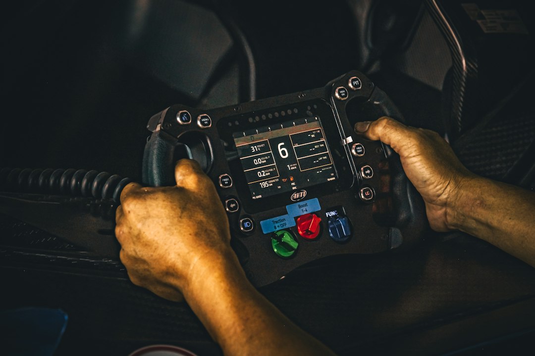
When live data points to the ECU or actuator
If commanded angle changes but the throttle motor draws abnormal current or the motor doesn’t respond while wiring checks clear, the actuator (throttle motor) or its driver inside the ECU is suspect. Some scanners can run motor actuation tests—use that to isolate motor vs. wiring. If the motor runs but plate movement is weak, inspect shaft bushings and linkage for wear or binding.
Deciding repair vs. cleaning vs. replacement
- If PID errors are due to noisy signal but wiring and connector repair fixes the reading—replace the sensor only if the noise remains.
- If cleaning restores smooth PID response and commanded/actual alignment, save cost by cleaning and performing a relearn.
- If the motor fails actuation tests or multimeter checks show open/short in the motor windings, replace the throttle body assembly (or motor if serviceable).
- If ECU-level actuator drivers appear faulty and wiring is good, plan for module repair or replacement after verifying costs and dealer diagnostics.
One recommended tool for confident live-data diagnosis
For most technicians and advanced DIYers needing reliable live data, a mid-level live-data scanner with bi-directional capability speeds diagnosis.
Quick practical checks before ordering parts
- Record a short live-data log while replicating the issue—saves time if you later consult a shop.
- Check for stored DTCs beyond generic PIDs—matching trouble codes narrow the subsystem (TPS codes vs. throttle actuator codes).
- Try a temporary cleaning and relearn before replacing the throttle body on high-mileage cars with carbon buildup history.
- Capture baseline live PIDs: TPS, commanded angle, RPM, MAF/MAP, fuel trims.
- Compare commanded vs. actual throttle position during manual and scanner-driven tests.
- Inspect for carbon at throttle plate and clean if binding is visible.
- Use multimeter checks at the sensor connector to verify 5V reference and signal continuity.
- Run actuator command test if scanner supports bi-directional control.
- Perform ECU throttle relearn after cleaning or replacement.
Live diagnostic data turns throttle symptoms into concrete evidence: use commanded vs. actual PIDs first, verify wiring/sensor voltages next, then inspect/clean the plate, and finally run relearn or replace parts only when tests point there. A good live-data scanner will shorten diagnosis and avoid unnecessary parts.
Can a dirty throttle body throw a check engine light?
Yes—carbon-caused sticking can trigger throttle actuator or throttle position fault codes, but sometimes it creates drivability symptoms without an immediate CEL.
What PID proves the throttle motor is working?
Commanded (target) throttle angle versus actual throttle position: if commanded changes and actual follows, the motor and driver are functioning.
Will cleaning always fix throttle position mismatches?
No. Cleaning helps when the plate is stuck or sluggish from deposits; it won't fix failed motors, worn linkages, or bad wiring/ECU drivers.
Do I always need a dealer scanner for relearn?
Sometimes a generic scanner can run relearn; other makes require dealer-level access. Check your vehicle’s service info and your scanner’s capabilities.
How do I know if a TPS needs replacement rather than wiring repair?
If bench and connector voltage tests show unstable or jumpy signal despite solid supply and ground, the TPS itself is likely failing and should be replaced.